 |
 |
 Excerpt from the original Western Electric 300B data sheet.>
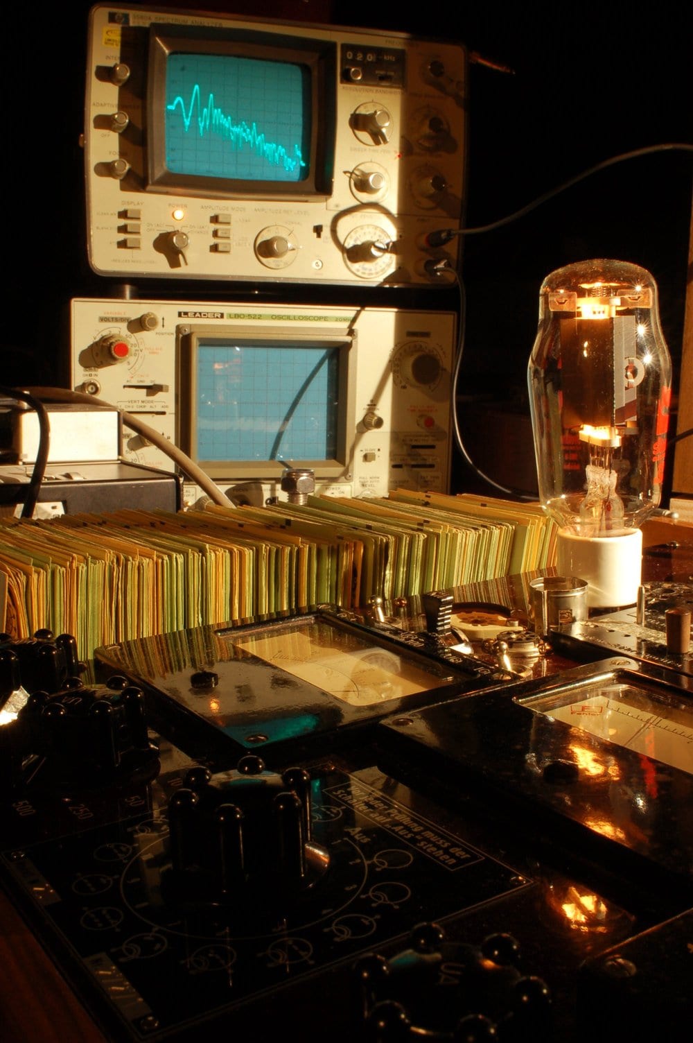 A transmitting triode tube in the lab, undergoing testing. Photo courtesy of Agnew Analog Reference Instruments.
|
|
Excerpt from the original Western Electric 300B data sheet.> A transmitting triode tube in the lab, undergoing testing. Photo courtesy of Agnew Analog Reference Instruments.
“Where words fail, music speaks.” – Hans Christian Andersen In this issue: I have a first look at Florida Audio Expo 2025. Octave Records releases its latest album: jazz pianist...
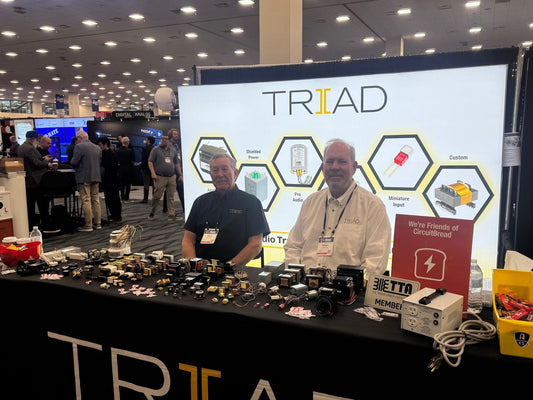
Triad Magnetics is one of the world’s foremost manufacturers of transformers for audio, musical instrument, and industrial applications. Founded in 1943, Triad is based in Perris, California and offers thousands...