At the heart of all phono cartridges we will find a transducer that translates mechanical motion – the movement of the stylus and cantilever as the stylus traces the record groove – into an electrical signal. The general principle of operation is electromagnetic induction. There is a magnetic circuit consisting of iron, one or more permanent magnets, and coils of wire. Relative motion between these elements generates a signal. This implies that any of the elements can become the moving element while the others can be the stationary elements.
As such, moving magnet, moving iron and moving coil cartridges have all been widely available for several decades now. They all operate on similar principles but have fundamental differences, especially regarding the possibilities of practical implementation.
Moving Magnet Cartridges
In the moving magnet system, the moving element is a permanent magnet, attached to the cantilever. The magnetic circuit and coils remain stationary and convert the fluctuations in magnetic flux density caused by the moving magnet into an electrical signal. The signal level at the output depends primarily on the strength of the magnet and the number of turns in the coils. Magnet strength is generally proportional to magnet size and magnets in general tend to be heavy. To maintain a low moving mass, the magnet must therefore be kept small. This limits the magnet’s strength, and if it would be made too small and weak, it would become very difficult to obtain a decent output.

Audio-Technica AT12XE moving magnet cartridge cantilever close-up.
So, moving magnet cartridges have to have a certain minimum of moving mass, which tends to limit their performance at high frequencies. Given that the magnets are not very strong, the number of turns in the coil tends to be high to provide a healthy output, typically 5 mVrms per channel for an rms lateral velocity of 5cm/s at 1 kHz. A large number of turns results in high inductance, which is necessary to provide the required output level. This results in a high impedance, requiring a high input impedance in the phono preamplifier, typically terminating the cartridge with a load resistor of 47 kOhm. A large number of turns will also result in distributed capacitance between layers and turns of wire.
The tonearm wiring and interconnects to the phono preamp add to the total value of capacitance, and the preamp itself usually provides certain values of load capacitance in order to fine tune the high frequency response of the setup, which tends to exhibit a high frequency resonance due to the presence of the LCR resonant circuit (inductance, capacitance and resistance; “L” is the electrical symbol for inductance) created by the cartridge, interconnects and preamp.
In the better designs, the high frequency resonance can be adequately damped so as not to cause a peak in the output, but then the high frequency response above the resonant frequency sharply drops. This resonant frequency is usually just above 20 kHz in good moving magnet cartridges, or even below that in the less-exciting specimens. In addition, as the number of turns in the cartridge coil increases, the length of wire increases, in turn increasing the resistance along with the inductance, which both have an adverse effect on the self-noise of the cartridge. Along with the total capacitance, the 47 kOhm termination resistance and the other parameters of a practical preamplifier implementation set the lower limit of noise that can be achieved.

AT12XE dual magnet assembly close-up.
Photo courtesy of Agnew Analog Reference Instruments.
Lower inductance and resistance would result in lower output, which would make it difficult to realize improvements to the noise of the system, which, for a practical high-quality, low-noise moving magnet setup, would be almost equal to the noise contributed by a silent groove on a record. This would be acceptable for most domestic uses, but perhaps worth improving upon for professional or highest-fidelity audiophile applications to be truly medium-limited, (in other words, where the noise level of the disk medium itself is to be much higher than the noise of the entire reproducing chain) with a bit of a safety margin on top.

AT12XE pole pieces visible with cantilever assembly removed.
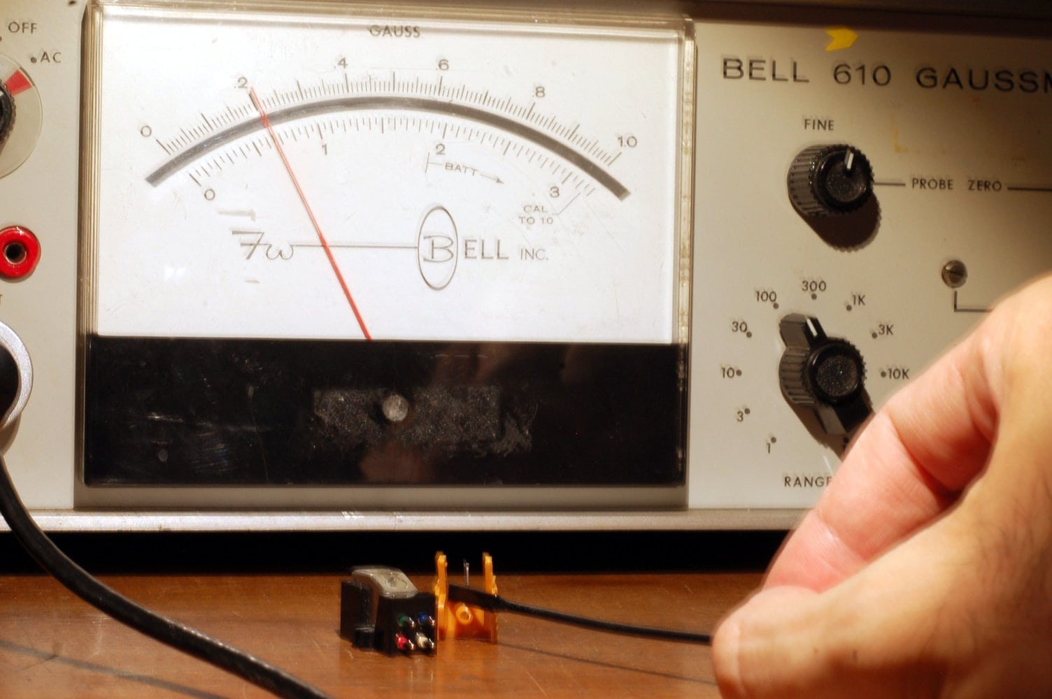
AT12XE dual magnet assembly and Bell 610 gauss meter.
Photo courtesy of Agnew Analog Reference Instruments.
Moving Iron Cartridges
In moving iron (aka variable reluctance) cartridges, the magnet is stationary along with the coils and the biggest part of the magnetic circuit. A small part of the magnetic circuit, usually in the form of an iron ring, is attached to the cantilever and moves with it.
At the rest position, the net magnetic moment of the iron ring is zero. As it moves and approaches a magnetic pole piece, the ring becomes progressively more magnetized, upsetting the system equilibrium (causing changes in reluctance) and generating a signal voltage in the coils. If the ring then moves in the opposite direction, it first becomes demagnetized as it passes the rest position and magnetized again in the opposite direction (reversal of the magnetic poles), reversing the polarity of the induced electromotive force (EMF).

Internal view of the Grado Statement moving iron cartridge.
Photo courtesy of Epos Laboratory Retip.
With the magnet and coils being stationary, it would be tempting to assume that they could be dimensioned (sized) as needed with no need to consider their effect on the moving mass. However, increasing the size of these components would result in an increase in the magnetic flux density of the magnetic circuit, which would require an increase in the size of the moving iron ring as well, to prevent it from becoming magnetically saturated, which would result in gross distortion. Looking at it another way: although the magnet itself is stationary, its strength still affects the moving mass of the system via the iron ring. To keep the moving mass of the iron ring-cantilever-stylus assembly reasonably low, the moving iron volume must be kept low, imposing strict limits on the magnetic flux density permissible prior to the onset of saturation.
We are therefore back to a similar situation as in the moving magnet system. We need a larger number of turns in the coils to provide a reasonable output level, which is again typically 5 mVrms per channel for a 5 cm/s lateral velocity at 1 kHz. The same LCR resonant system considerations apply here as well.

Coil assemblies from a dissected moving iron cartridge.
Photo courtesy of Agnew Analog Reference Instruments.
Due to the magnetic hysteresis curve of the soft magnetic material that the moving iron piece is made of, the magnetization and demagnetization that occurs in a moving iron design is not a linear process. This tends to produce higher distortion.
Some manufacturers of moving iron cartridges have introduced high performance low output models. The output level is intentionally reduced, to improve linearity (at the expense of noise), to reduce the moving mass, or to make the LCR resonant circuit parameters more favorable, extending the high frequency response to some extent.
Moving Coil Cartridges
The moving coil configuration, as the name would imply, consists of a stationary magnet and magnetic circuit. The coil assembly is attached to the cantilever and moves with it. There are no restrictions placed on magnet size, weight and strength, as long as it can still fit in a package that can pass for a cartridge. Indeed, moving coil cartridges often use much more powerful magnets, making them incompatible with turntable platters made of ferromagnetic materials such as cast iron. The cartridge would be attracted towards the platter and it would be impossible to set the vertical tracking force (VTF). Moreover, any surface variations in the platter would likely be translated into sound!
The powerful magnetic circuit permits coils of fewer turns to be used. Copper (the material the wires are frequently made of, not the magazine! OK, perhaps also the magazine…) is rather heavy, so in the interest of keeping the moving mass low, it is common to use very few turns in the coils, resulting in very low output, typically 0.5 Vrms per channel (for 5 cm/s rms lateral velocity at 1 kHz). This is a full 20 dB lower than a typical moving magnet cartridge! Additional amplification is required and it is not a trivial matter to achieve it, together with exemplary low noise. However, the significantly lower inductance and wire resistance does a lot to help in the practical implementation of a low noise system and moving coil cartridges have much lower self-noise than the other types. The impedances involved are much lower and we also no longer need the 47 kOhm termination.

EMT TDS15 moving coil cartridge.
Photo courtesy of George Vardis.
The lower number of turns means that the capacitance between turns is negligible. There is still the wiring capacitance on the way to the preamp, but the inductance is so low that the LCR effect is also insignificant within any conceivable notion of audio frequency range. As a result, I have personally measured moving coil cartridges demonstrating a frequency response that was reasonably flat to at least 50 kHz, this being the limit of the sweep on the test record used.
There are also higher-output moving coil cartridges available, going as far as 2.5 mVrms per channel (5 cm/s lateral velocity/ 1 kHz ref). This is either achieved by using a stronger magnet, or more turns, or both. The higher output is easier to deal with from a circuit design standpoint, but may come at a penalty of higher inductance, self-capacitance, or moving mass. Having said that, one of the moving coil cartridges that could go up to 50 kHz was a high output model, so the good ones are worth looking into!

Brass insert to a low cost plastic bodied cartridge, demonstrating the importance of the total mass.
A moving coil transducer is incredibly linear and detailed, but much trickier to make.
Since the coils move, there are tiny wires going from the moving system to the output pins, which must not impede motion and must remain intact. Considering the importance of low mass, it can be understood that the wire used is extremely thin, so these cartridges tend to be fragile!
My personal preference for phono cartridges is moving coil, but I do also use a couple of old faithful moving magnet cartridges to double check my test cuts and the resulting pressings. I remember when a vintage General Electric VR-II cartridge reached my lab some years ago. It called for a vertical tracking force of 4 grams (!) and with its rotating stylus selection system (to choose between standard groove and microgroove styli, did not exactly look convincing. I tried it on a modern full-range recording, expecting a laugh, but was instead blown away by the punch it packed and how gracefully the cartridge handled it!
There are multiple paths to good sound and all three transducer types discussed have found application in professional audio facilities through the years, and used as references. Keep in mind, though, that it is not just the cartridge alone, it is the entire phono playback system that produces the end result.