


 The first step in beginning a new project is constructing the pattern from which the fiberglass mold will be laminated. The above picture shows the various sheets of ¾” MDF (medium density fiber board), that is glued and clamped together.
 After the clamps are removed and the excess glue is sanded from the sides of the block, a layout is drawn on the top surface of the pattern. The next step is to cut the angles so that we can proceed along the lines of building up the pattern. Since a fiberglass mold will be pulled off this pattern, a two-degree angle is machined on all sides so the part can be easily removed from the finished fiberglass mold. If the two-degree draft is not cut on the sides of the pattern, the fiberglass mold will lock on and the two can never be separated.
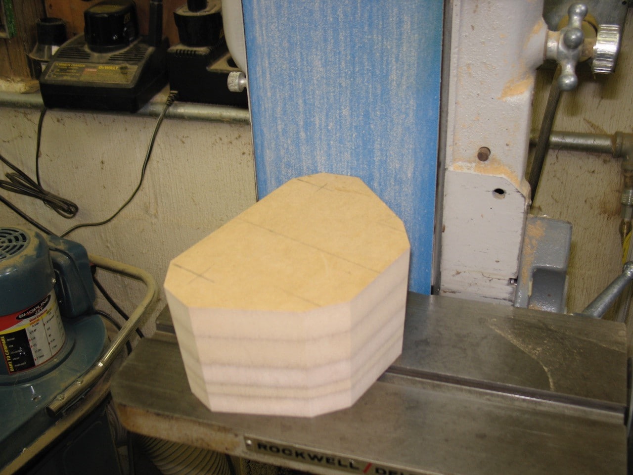 Shown above is one of the three blocks machined out to replicate the size and shape of the three arm pods. Two-degree draft is being sanded on all of the surfaces to ensure that the final pattern can be demolded from the fiberglass mold.
 Pictured above is the overall design of the table plinth with the 3 arm pods correctly positioned before being glued together. The arm pods, as you may be able to tell, have also been cut with two-degree draft on all sides.
 This photograph shows the application of a thin sheet of slate textured formica on alternating edge surfaces of the three arm pods and center pattern section. This is being applied just for aesthetic reasons so that the final part does not have an antiseptic, industrial look to it.
 Here we see the three tone arm pods being glued to the center section of the pattern.
 This shows the finished pattern temporarily bonded to a glass plate. Then clay is put in the joint between the glass plate and the pattern with a 1/64” radius. This will prevent the epoxy gel coat from seeping under the pattern. A production mold can now be made from this pattern.
 Before the pattern can be sprayed with a grey surface coat, it must be coated with a mold release agent so that the two pieces can be separated when the lamination is completed. Here we see a polyester gel coat being sprayed to all surfaces of the pattern.
 You will notice dark areas around the edges and corners of the part being laminated. This is a mixture of polyester resin, cotton flock, and glass beads to form a paste that is brushed on all of the rough surfaces, inside and outside edges, and corners of the pattern. This is applied in order to prevent air bubbles from being formed in these areas during the first lamination of fiberglass, which you see depicted in this picture.
 In a few days, multiple layers of fiberglass and resin have been applied over the pattern to a thickness of approximately 3/16” of an inch. This becomes the performance surface of the final mold. In order to rigidize and stabilize all of the fiberglass surfaces that have been applied to the pattern, we will bond ¾” MDF pieces to all surfaces.
 The final step in finishing the production mold is to apply a box that is bonded with a polyester paste to the wooden reinforcement pieces that were applied to the 3/16” thick fiberglass laminate. The mold is now completed and the molding will be the next step.
 Here we see the pattern around which the production mold has been laminated. The glass plate has been removed and we are now ready to separate the pattern from the production mold.
 Here we see the production mold after the pattern (light grey color) has been removed. The production mold (dark color) will now be sanded, polished, and prepared to laminate the plinth for the turntable.
 Above you see the picture of the fiberglass part that has been laminated off the prepared master mold in the previous picture. It was laminated with the same fiberglass materials as was the production mold, but to a laminate thickness of ¼”. It was then trimmed out, polished, and placed on the board you see above so that it can be used to produce a replica shape of what will be machined from solid aluminum.
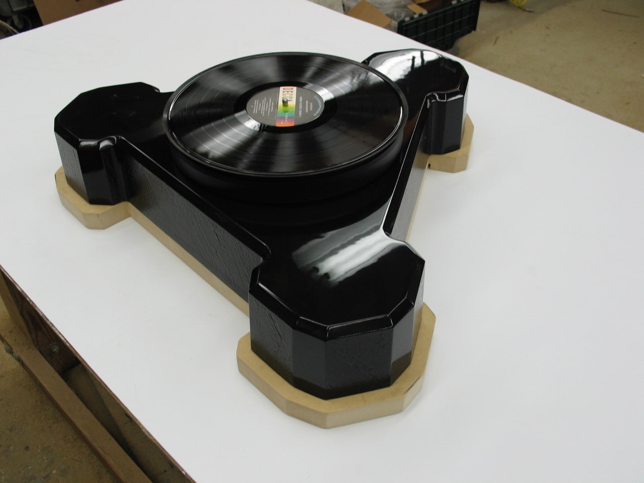 The MDF sub-plate you see pictured above will be sent to a machinist who will duplicate this part 1 ½” thick type 6061 aircraft aluminum.
0 comments